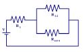
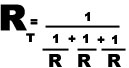
series-parallel circuits  

Most loads installed by electricians such as lighting and heating systems, motors and such are installed in parallel. This is because the supplied voltage remains constant and is NOT divided up over the loads. Your home is connected in parallel with your neighbors home!
Switches are installed in series so that they open and de-energize a circuit.
In digital electronics transistor switches are connected in series and in parallel to create the fundamental logic gates AND and OR.

SERIES CIRCUITS PARALLEL CIRCUITS
                              CHARACTERISTICS

- one path of current flow
- REMOVE 1  LOAD - current flow stops in all loads
- voltage drops across each resistor

- VT     =    V1  +  V2  +  V3

- I T     =    I1 =  I2  =  I3 ...

- RT     =    R1 + R2 + R3 ..........

                                     CHARACTERISTICS

- many paths of current flow
- REMOVE a load - current continues to flow in others
- voltage the same across each load
 

- VT      =     V=  V2  =  V3 ........

-
I T     =     I+  I2  +  I3 ...

_ 

Circuits calculator  simulator link    speakers in series and parallel

Resistor Cable Resistance calculator simulator link

Complex circuits have combinations of series and parallel loads and can be solved using the rules above and converting the circuit into an equivalent series circuit.