transistor switching

The other important use for the transistor is as a switch. Unlike mechanical switches and relays they do not wear out, and can be controlled electronically. However they  cannot switch safely or cost effectively over 50A loads.
Automation of systems is possible as
computers can be programmed to control transistors that then control other small power loads or devices such as relays that control higher current power loads.


closing the switch forward biases the transistor which then energizes the LED


When the Duff beer N.O. proximity switch is closed the transistor is forward biased, this energizes
the relay coil closing the N.O. contact. Now the LED circuit is closed and the LED is energized.
( the diode beside the relay coil eliminates some of the coil's inductive kickback )

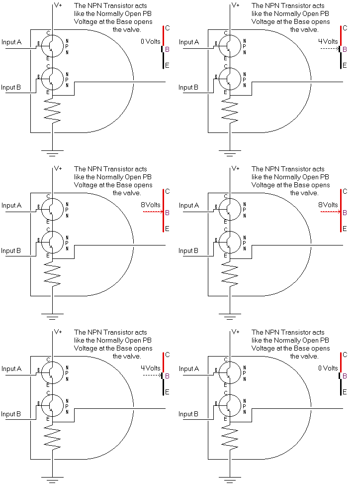
Digital logic is made possible by transistor switches and are the basis of the logic gates that comprise ALL digital devices.
The extreme speed at which solid state devices can be switched has enabled the CPU, routers and other devices that make computers and the Internet possible

The AGE of POSSIBILITY is driven by the transistor!


Digital Application of Transistor Switching


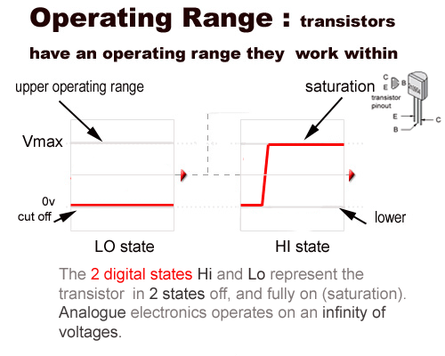
In the binary number system there are only 2 numbers ... zero and one
0 =
Lo
1 =
Hi


H
ere is a light activated transistor switch.

a) light falls on the photoresistor and the resistance drops

b) current then flows from the base circuit forward biasing E-C

c) E-C is forward biased and current flows energizing the LED circuit.


The transistor controlled buzzer circuit is activated when a normally closed (NC) push button is opened.

When the push button is closed it clamps the E-B junction at 0 volts preventing biasing of the E-C circuit

Opening the switch allows current to flow across the E-B circuit forward biasing the transistor


Phototransistors have an exposed base

When exposed to light the photo electricity generated forward biases the the junction
turning the transistor on

Phototransistors are used in Optic - Isolators that transmit signals between two stages and prevent mixing of different voltages


Here is the termination of a Fiber Optic Cable
being coupled to a Phototransistor where the
digital light signal will be converted to an
electronic signal


OPTOCOUPLERS


The Optocoupler above is used to isolate the low voltage control circuit (left) from the high voltage motor control circuit (right)

Schematic of an Optocoupler circuit : when the S1 is closed is
closed it energizes D1 LED whose light forward biases Q1 transistor
                          Optical isolator chip
incoming signal is electrically isolated from the outgoing signal

Most of digital electronics is based on transistor switching to perform binary functions at high speed.
The binary numbers are 1 and 0 equivalent to the 2 electrical states in digital electronics:

OFF
  or  ON  
HI   
 or  LO