I
was paid
this Thursday
AND
my girlfriend's available ....... the
date is ON.
The ethanol tank is correct temp.
AND
container is in correct position ......
FILL NOW.
That's logic .... one set of conditions allow for some other event to be
true.
Logic was developed when
Aristotle (384 to 322 BC) wrote a book covering the art of discourse
called the Organon (meaning instrument or tool) about the
methodology of logic.
In order to control a process (the date) conditions must be met and a
final decision made based on the inputs conditions.
In 1854 George Boole (1815-1864) unified algebra and
functional logic in his book, The Laws of Thought, by creating
Boolean algebra which uses
numbers to represent truth values.
Thus "true" is usually represented by
"1" and "false" is represented by "0".
Truth Tables invented by
philosopher
Ludwig Wittgenstein are a device used to account for all possible
logical input states and the logical
output states.
In
electrical theory a circuit is energized or it is not
1 represents
ON (HI)
0 represents
OFF (LO)
Introduction to
digital logic gates and the
circuits that make them
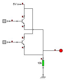
 This
is a digital logic AND gate built from 2 NPN
transistors connected in series This
is a digital logic AND gate built from 2 NPN
transistors connected in series
When both inputs A
AND B go HI
(connect to positive) the output goes
HI
If one input is Lo then the
output is Lo
Both A AND B
must be Hi for the output to go
Hi
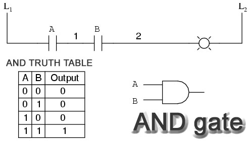
The
AND gate is like 2 switches in series unless
switch A AND B are closed (like the
transistors above and below) the load is not energized.
Truth
Tables
list the possible states that can exist at the input and the
resulting logic output.
 |
Follow this animation several
times until you intuitively understand what is happening at the input and
the output. |
|
The LED will not turn on until
the output goes positive Hi to complete its circuit.
The only way for the output to
go Hi is for both transistors to turn on completing the circuit. |
|
For both transistors to turn
on both must connect their bases to the Hi input. This allows base current
to flow which forward biases the 2 transistors on.
|
The
7408 DIP (dual inline package) 14 pin
chip
contains 4 separate AND gates
NOTE: pins 14 and 7 are the source power pins
 Here
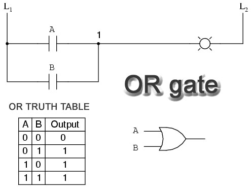
is an OR gate which sends its output Hi when either input goes Hi Here
is an OR gate which sends its output Hi when either input goes Hi
The OR
gate is like switches in parallel if either switch is closed the output
will go Hi
You might have
guessed that the OR gate is constructed using 2 transistors connected in
parallel
 |
Digital OR circuit
made from 2 switches in
parallel |
 |
Here is the
internal construction of an OR gate
made of 2 NPN transistors connected in parallel
|
The
7432 chip is a 14 pin DIP chip contains 4 OR gates
Combine the NOT with an AND and you get a NAND
combine the NOT with an OR and you have a
NOR
- put 2 invertors together in
series is like a double negative in language so the output is the same as
the input and the current is amplified
- this NOT NOT correct!!
 This
Combinational Logic circuit shows 3 inputs that combine to determine the
state of the output which might be a light or motor etc control circuit This
Combinational Logic circuit shows 3 inputs that combine to determine the
state of the output which might be a light or motor etc control circuit
below is the same circuit in a simulation with a converter tool attached
Lady Byron |

