| | SCRs | 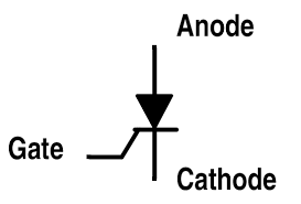 
The
SCR is a controllable DIODE. It needs
a current signal from the gate to turn on and once turned on it will stay
on until the voltage across cathode - anode returns to 0v.
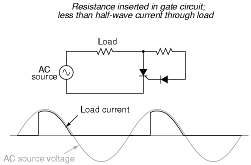
In
AC circuits they can be "triggered on" at a
particular voltage point on the sine wave and they will continue to conduct until the wave
crosses the 0v pointand then stop conducting until triggered again at the next trigger point on the sine wave.
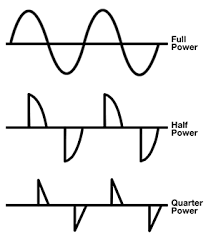
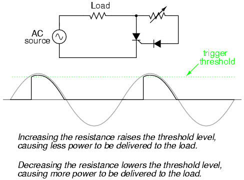
By slicing the sine wave, RMS power can be
controlled on AC loads such as lights and motors.
In
AC circuits inverted parallel pairs must be used together (to allow for AC
conduction).
Banks
of SCRs can be combined to
increase the power rating of a control system.
SCRs cannot amplify or switch in the same
manner as transistors.
Notice the TO220 has the tab (with bolt hole)
as the Anode
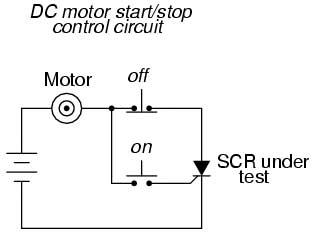
A
simple stop start
control circuit can
be built for a DC motor from an SCR.
When
the NO (normally open)
ON push button is
closed the SCR begins to conduct energizing the motor.
The motor will continue to run even when the ON button is released
because an SCR will conduct once energized until they are
de-energized.
Opening
the NC (normally
closed) OFF button will
de-energize the circuit opening the SCR circuit and stopping the motor.
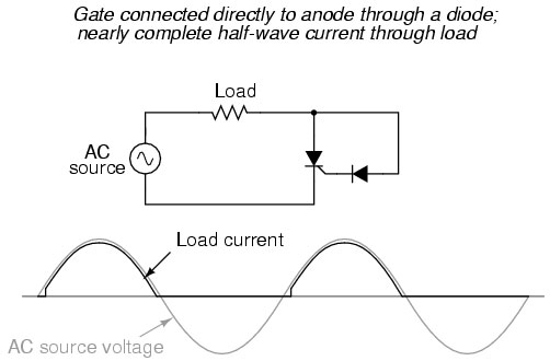
One SCR in an AC circuit
triggered by a diode will create pulsating DC.
The little notch on the PDC wave reflects the .7V forward voltage of a
diode.
|

 SCRs silicon controlled
rectifiers
SCRs silicon controlled
rectifiers